Stirling Engine
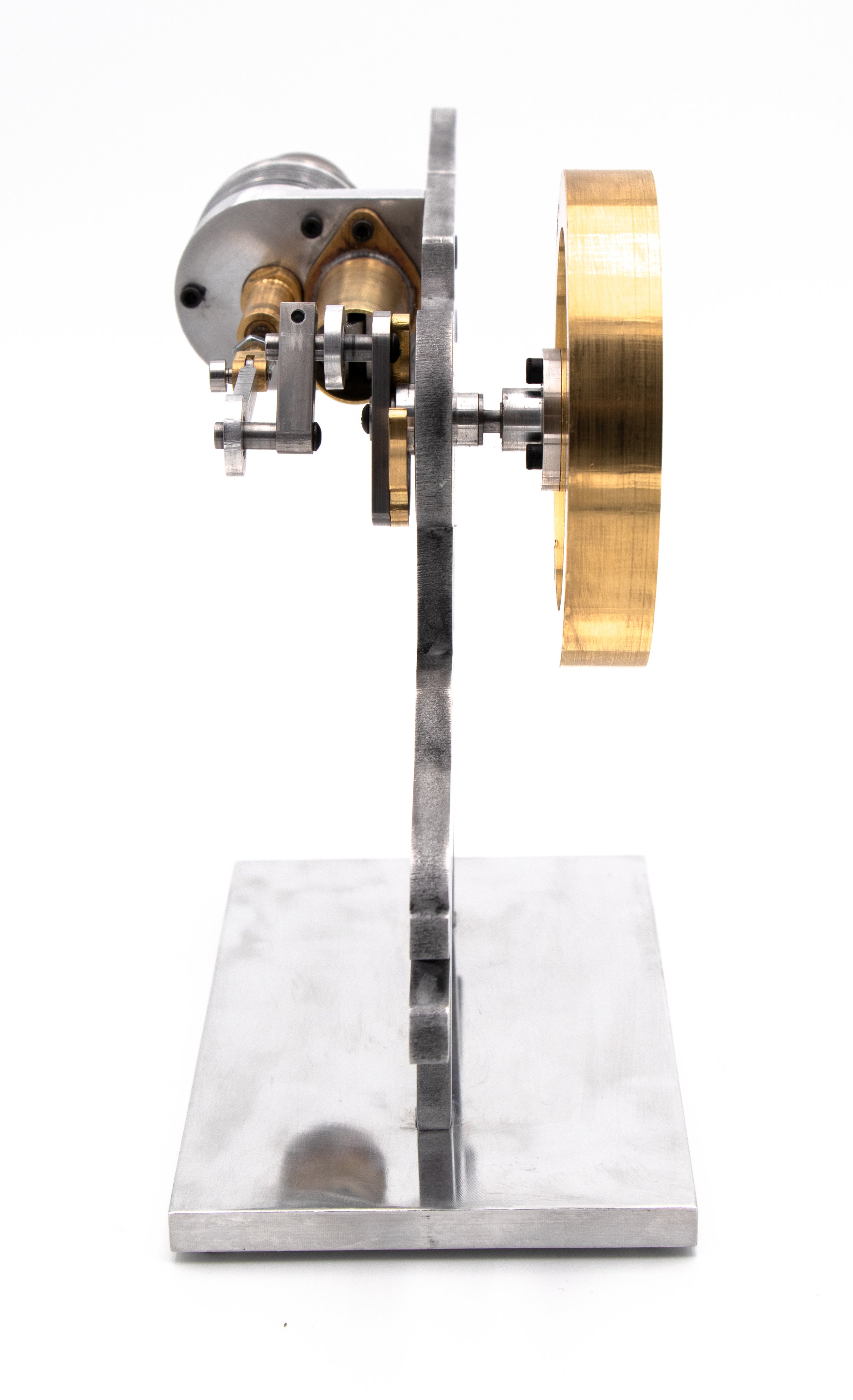
A Stirling Engine is a heat engine that works by compression and expansion of air at different temperatures, turning heat energy into mechanical work. This Gamma type Stirling Engine was designed and manufactured over the course of a semester.
Click HERE or scroll to the bottom for the engine testing video!


Main Steps
-

Design
The design step includes the initial brainstorming of engine ideas, SolidWorks CAD assembly, 3D renderings, and finally making all the engineering drawings and choosing the appropriate tolerances given the functionalities.
-

Fabrication
This step includes the manufacturing of all parts necessary for the engine and making sure everything is below tolerance and deburred. Main materials include 6061 Aluminum, C360 Brass. and Stainless Steel.
-

Test
The testing step includes putting the engine together, lapping and oiling certain parts, polishing parts for aesthetics, and finally testing the engine by applying heat. Scroll to the bottom for a cool testing video!
Design
I decided to go with a 007 James Bond-themed design, not only as a loyal fan, but I also think it would be cool that the engine will be completed around the same time as the new 007 movie – No Time to Die – will be released in the US.
Below please enjoy some 3D rendering images of the design with KeyShot.


Manufacturing
In this section, you will find pictures and brief descriptions of the manufacturing process of most parts of the engine.
1. Mounting Block
Mounting Block is the first and one of the hardest parts we had to make. Featuring: hole making (countersink, counterbore, angled holes, threading, reaming) face milling, CNC, Conversational Programming


2. Piston Flange
Featuring: MasterCam


3. Web (more pictures to come)
Featuring: ProtoTrak Tookpath, Fixturing

4. Piston
Featuring: Facing, turning, grooving, slitting saw, chamfering, micrometer


5. Displacer Rod Fork
Featuring: Corner rounding tool


6. Crankshaft Bearing Tube
Featuring: Micrometer, turning, facing


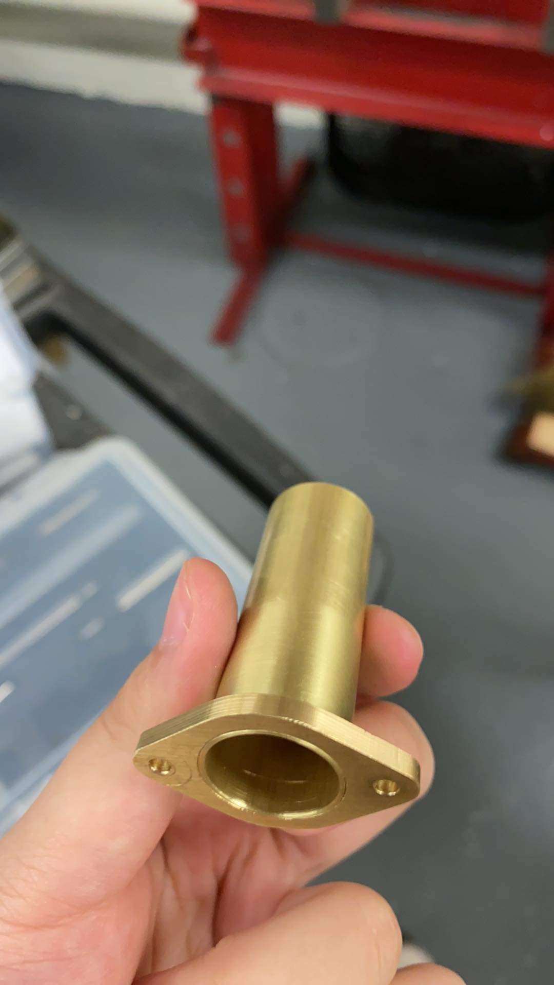
7. Displacer Bushing Tube
Featuring: Exterior thread making


8. Balance Weight
Featuring: Customized Fixture, CNC Toolpath


9. Connecting Rods - Piston Connecting Rod & Displacer Connecting Rod
Featuring: Customized Fixture, CNC Toolpath


10. Bedplate
The bedplate is sent out for waterjet. It was not manufactured in-house.
Secondary operations include adding a countersink, reaming, and sanding and polishing.


11. Heat Sink
Featuring: 3 Jaw Chunk, V-Block, Dial Indicator (not pictured)


12. Hub
Featuring: Collet Block


13. Output Shaft
Featuring: Stainless Steel


14. Flywheel
Featuring: Soft Jaws, Prototrak Toolpaths, MasterCam Toolpaths


Testing
We finally put together our engines after a semester of hard work! This step includes more sanding, polishing, oiling, trouble-shooting, and more. Enjoy a quick clip of the first time we tested the engine!
Appendix. GD&T - Tolerance Stack-Up Calculations
Prompt: You have been contracted by a hypothetical company to refine the engine design for mass production. The company is automating the assembly of the heat engine and wishes to avoid manual/QC adjustments to the assembly. It is believed that the displacer is oversized and assembly can result in contact between the displacer and the air chamber in a worst-case assembly scenario.
Goal: We were asked to perform an on-paper, worst-case tolerance stack up to determine the maximum displacer diameter that prevents interference/rubbing between the displacer and the inner diameter of the air chamber.
Click the button below to access the engineering drawings of related parts & calculations.