Balto
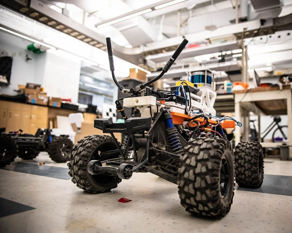
The Radio-Controlled (RC) car is one of the main vehicles that the CoSTAR team used in the first circuit (Tunnel Circuit) of the DARPA challenge. The RC Car was named Balto after the famous Siberian husky sled dog who delivered diphtheria vaccines to kids from Anchorage to Nenana, Alaska through a huge storm. RC Balto is equipped with numerous sensors, including Lidar and RealSense cameras. Designing and installing dust and water-resistant shields, ventilation tubes, and mounts for RealSense cameras and flashlights were all team projects for this vehicle.
*Background image here from news linked below
Ventilation Tube
The ventilation tube was designed to aerate the new waterproof and dustproof housing of Odrive motor controller in the RC car. When designing the tube, we ran into some problems due to 3D printing. Even though the tube looked correct in STL preview, some areas had thickness so close to 0 that the 3D printer did not print it at all, leaving holes in the walls of the tube. I made changes to construct a smoother curve, creating more sketches to guide the loft cut and making sure the thickness was sufficient for printing. While initially difficult, I was able to remove the supports with a flat screwdriver, hammer, pliers, tweezers, and time.
Camera Mount
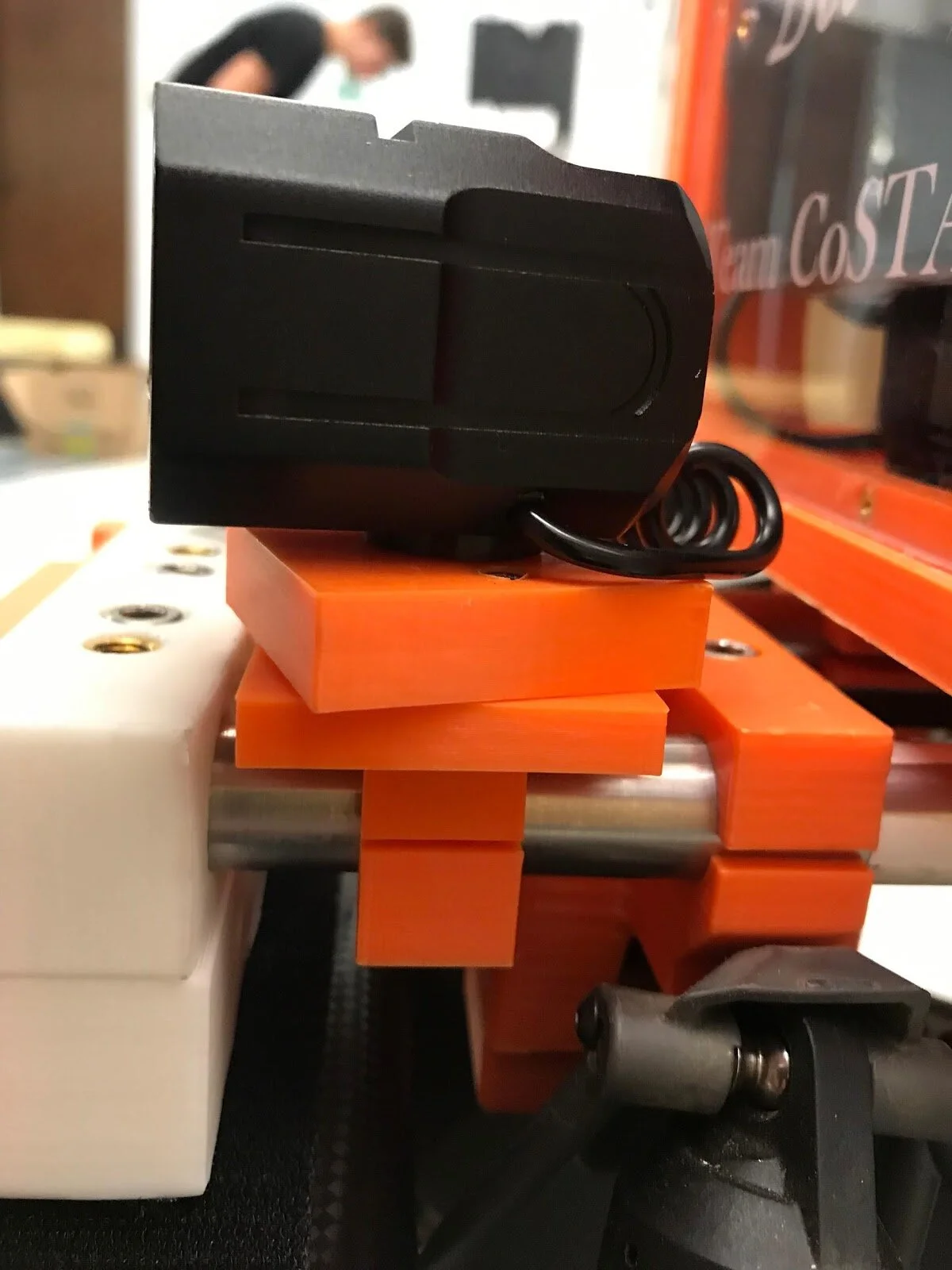
The next step of the project was to design a release mount that places the Realsense T265 (T for tracking) and D435 (D for depth) camera that is used for object detection on top of the lidar unit, the highest point of the robot, to provide the best angle for object detection purposes. After testing at Eagle Mine, the team discovered significant damage to camera cables and cable connections due to uneven ground.
The team created a newly designed mount to relieve stress on the cable plug by keeping the cable and the micro USB port on the camera at the same surface level, avoiding cable bending at the most critical points. After the initial design, two other camera mounts were modified to place at different positions relative to the Lidar. The main shape was unchanged with modifications to the width, length, height, and hole positions for the mount to fit onto other places, allowing the final assembly to have a variety of camera positions tuned to the specific tasks.
Flashlight Mount
Originally, the flashlight mount was designed to be clipped onto the rod. However, it snapped into pieces due to the lack of strength and flexibility of the plastic parts (shown at top).
To solve the problem, we
decided to print it in two pieces, with screws holding them together. The top pieces also make it possible for the flashlight to be repositioned at 10 different angles for each particular task, which is possible by placing ten screw holes with heat inserts onto the mount, with the flashlight using only two of them for every fixed position.
The top pieces also make it possible for the flashlight to be repositioned at 10 different angles for each particular task, which is possible by placing ten screw holes with heat inserts onto the mount, with the flashlight using only two of them for every fixed position.
See Caltech News Release for more on this project.

Communication Node

RealSense Camera Mounted

Flashlight Mount (Side View)

Communication Node Mount

Temporary Dust/Water-Resistant Shield

Module Mounter


