Mechatronics: Grand Theft Autonomous
This is the final project for MEAM 5100: Design for Mechatronic Systems. In a team of three, under strict budgetary constraints of $150, we built a robot that can autonomously navigate, manipulate objects, track beacons, and offer manual control via a user-friendly interface, all powered by ESP32 microcontrollers and wireless communication.
Game Rules
Robot Control: Robots are controlled wirelessly using ESP32 microcontrollers, and players must rely on sensors and communication for gameplay. Players cannot see the field, and most of the game is autonomous.
Initial Robot Size: Robots must fit within a 12” x 12” x 12” box.
Communication: Robots can transmit a maximum of 10Kbytes/sec of data each way. Communication is vital for gameplay and scoring. The total number of packets received determines a communication multiplication factor, impacting the final score.
Scoring Objects:
Trophy: One Trophy object on each side emits IR light, with specific frequencies for each team. Securing the Trophy is crucial for scoring.
Fake Object: Similar to the Trophy, there is one Fake object on each side that emits IR light. Teams must distinguish between the real Trophy and the Fake object to maximize points.
Police Car: A Police car is positioned in the center of the field and serves as another scoring object. Teams earn points by moving the Police car.
Double Points: Special scoring zones, known as the "2X area," offer double points for objects placed within them.
Object Placement: To score, objects must be entirely over specific lines on the field, requiring precision in placement
Mechanical Design
Mecanum Wheel Drive: Enabled omnidirectional movement for precise positioning during competitions.
High-Torque Motors: Chosen for effective pushing of objects, crucial for the robot's functionality.
Custom 3D-Printed Adapters: Designed to fit the specific motor shafts.
Single-Piece MDF Chassis: Offered a solid base for mounting components and maintaining overall stability.
Integrated Design Approach: Seamlessly combined with the electrical and control systems for effective operation.
Electrical Design
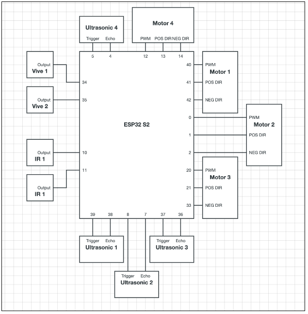
Ultrasonic Sensors: Positioned on each side of the robot, this enabled tasks like wall-following without the need to turn, enhancing navigational capabilities.
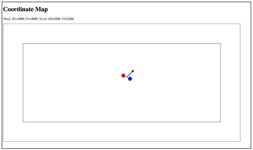
Vive Sensors: Used for precise positioning and orientation, crucial for maneuvering and target alignment.
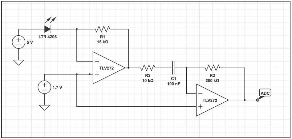
IR Phototransistors: Facilitated effective beacon tracking of 23Hz and 550Hz signals, a key aspect of the robot's autonomous functionality.
Flex Sensors: Although not used in the final design, these sensors were prepared to detect contact with objects, demonstrating foresight in design.
Motor Control: Managed using SN754410 Quadruple Half-H Drivers, ensuring smooth operation of the mecanum drive.

IR Circuit

Vive Circuit
Processor and Code Architecture
Processor Selection: We chose the ESP32S2-DevKitC-1 microcontroller unit (MCU) for its enhanced capabilities, specifically the increased number of pins which was essential for connecting the multitude of sensors and the four motors required for the mecanum wheel drive.
Structured Modular Code Design: The software was organized into distinct subroutines, each handling a specific function like wall-following or beacon tracking. This modular approach allowed for efficient debugging and easy switching between different modes of operation, such as autonomous and manual controls.
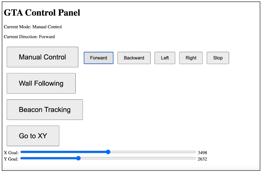
HTML-Based Control Interface: An HTML webpage was created with buttons to enable easy mode switching. This interface not only allowed for the selection of operational modes but also provided real-time feedback on the robot’s status, making the control more intuitive and user-friendly.
Coding Details of Different Operational Modes
Manual Control Mode:
Description: Allows direct control of the robot, overriding autonomous functions.
Coding Approach: The code for this mode primarily involved setting up direct input responses from the HTML interface. The user's inputs (forward, backward, left, right) directly influenced the motor driver direction pins, determining the robot's movement. Boolean variables were used to track the mode state, ensuring manual commands were only active in this mode.
Wall-Following Mode:
Description: Enables the robot to autonomously navigate by maintaining a set distance from the walls.
Coding Approach: This subroutine leveraged ultrasonic sensors to continuously measure distances from the walls. The code calculated the optimal movement direction (forward, sideways) to maintain a consistent distance (threshold set at 5 cm). If the distance exceeded the threshold, the robot adjusted its path accordingly.
Beacon Tracking Mode:
Description: Focuses on autonomously locating and moving towards a specific beacon signal.
Coding Approach: The robot utilized IR phototransistors to detect the beacon's frequency. The code was designed to rotate the robot until both sensors aligned with the beacon's frequency. Upon alignment, the robot moved forward towards the beacon. The code continuously adjusted the robot's orientation based on the sensors' readings to maintain the correct trajectory toward the beacon.
XY Coordinate Navigation:
Description: Designed to autonomously navigate the robot to specific XY coordinates on the field.
Coding Approach: This function aimed to orient the robot initially towards the +Y direction and then move sequentially in the X and Y directions to reach the target coordinates. The code calculated the necessary movement based on the difference between the current and target coordinates. This mode, while conceptually in place, required additional development for accurate and reliable operation.


